|
|
|
|
|
Polyphase
induction motor with solid-iron slotless rotor offers undoubted
advantages in terms of construction simplicity and strength over
conventional induction motors, even though its efficiency is much
lower. This solid-rotor motor is especially suited for applications
that require frequent starts.
Several Authors have
studied this solid-rotor induction machine using analytical methods
for a two-dimensional representation, by using either cylindrical or
Cartesian co-ordinate systems. The studies have been generally
restricted to the sinusoidal steady-state operation, even if an
analysis in terms of the two-reaction theory has been developed. The
major difficulty for a satisfactory analysis of the solid rotor
machine derives from the necessity to take saturation into account. In
fact, owing to the relatively small skin-depth, the rotor is usually
highly saturated. In the literature saturation effects are either
neglected or else procedures based on the choice of a trial and error
value for the average iron reluctivity are adopted. In the latter case
reference is usually made to the BI-H curve. This curve relates the
fundamental amplitude of
B to the
amplitude of H (which is assumed to be sinusoidal) and is derived from
the normal magnetisation characteristic B-H.
The finite element method,
on the other hand, allows the reluctivity of each individual iron
element to be evaluated. If the distortion introduced by the odd
harmonic components of magnetizing current is ignored, the sinusoidal
steady-state operation may be studied by the use of complex numbers.
If this is not done it becomes necessary to solve a time dependent
problem.
In this research, the
three-phase induction motor with smooth solid-rotor has been studied
by a two-dimensional finite element analysis. A machine with this kind
of rotor is particularly suitable for investigation by the finite
element method, since the machine geometry (as observed in a reference
frame on the stator) does not vary with the rotor motion.
Features of the study:
Ø Complete
representation of the magnetic behaviour of the iron in the machine
Ø Analysis
of the machine as a whole
Ø Determination
of the magnetic field for a given system of supply voltages.
Ø Prediction
of the performance under voltage-forced operation.
Ø Calculation
of every steady-state operating point as the asymptotic solution of
the electromagnetic field partial differential equation for a fixed
constant speed and for a given symmetric system of sinusoidal supply
voltages.
Ø Comparison
of the calculated electrical and mechanical quantities with
experimental results. |
|
|
|
|
|
|
|
The
linear actuators are increasingly employed as direct actuators in
servo systems replacing the more conventional mechanical systems.
The use of permanent magnets on the slider offers several advantages
associated with the absence of electrical connections and heating
effects due to copper losses. In addition, the use of a slotless
armature results in a simplified construction. The design of these
linear actuators is optimised for maximum force to total mass ratio
and for maximum force to moving mass ratio. In order to analyse the
dynamic behaviour a mathematical model based on a simplified field
analysis is developed. Numerical simulations of the step response of
a positioning servo system are now under investigation.
|
|

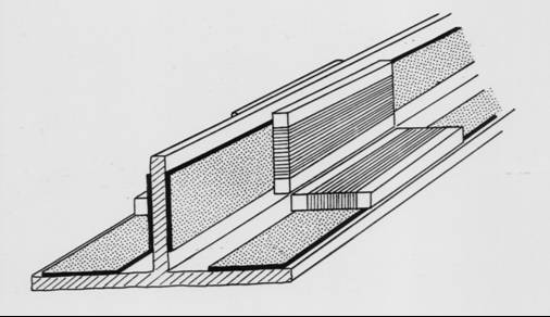
Fig. 1- Schematic drawing of the PM DC linear actuator.
 |
According to these
considerations a very simple and low cost PM DC linear actuator is
investigated which consists of a slotless armature and a permanent
magnet slider, as represented in Fig. 1.
It has been verified
that the magnetic circuit geometry allows the magnet to operate at
low demagnetising field if the Ampere-turns of the armature
winding are compensated. For this purpose, in addition to the
winding distributed over the working length, two coils are placed
at the ends of the actuator. The compensation of the armature
Ampere-turns is very important to achieve high thrust values. The
compensating coils can be replaced by distributed windings leading
to geometries which can drive two sliders. |
|
|
Simple linear models are not suitable to predict the performance of
the linear actuator shown in Fig. 1 as the stroke length is much
larger than the magnet length and the winding current is increased
beyond the rated value. Numerical techniques such as the
finite-element method can be used to determine accurately the actuator
performance, taking the non-linear behaviour of the iron circuit and
magnet material into account.

Plot of the flux density distribution |
|
|
|
Main Contribution |
|
|
|
Ø Two-dimensional
Finite Element field analysis
Ø Determination
of the effects of the iron core saturation on the thrust versus slider
position curve
Ø Calculation
of the peak force during temporary overload conditions
Ø Calculation
of the transformer and dynamic coefficients of the machine
Ø Definition
of the dynamic model of the linear actuator
Ø Compensating
coils replaced by distributed windings leading to geometries which can
drive two sliders
Ø Comparative
analysis |
|
|
MAGNETIC LEVITATION SYSTEMS
FOR HIGH SPEED GROUND TRANSPORTATION
|
|
|
|
The
research concerns the analysis of the vertical dynamics of an
electrodynamic levitation system using superconducting coils and a
passive and/or damping system.
In high speed magnetically
levitated vehicles the levitation systems based on repulsive forces
are statically stable but dynamically have zero or low damping
characteristics. In order to damp the vertical oscillations, passive
damping systems, constituted by short circuited coils placed under the
levitation coil, can be used. However, passive damping systems
usually do not provide the required ride quality. Then, the damping
effect on the mechanical oscillation of the vehicle should be
improved by using an additional active damping system.
The performance of combined
active and passive damping system has been evaluated. The active
damping has been performed by a coil current control using mechanical
or electrical transducers. It has been observed that, in general, the
control system based on mechanical transducers performs better than
that based on electrical transducers.
|
In the research, the
analysis of a control system for active damping which does not
require vertical position, velocity or acceleration measurement is
presented. The control system operation is based on sensing the
current in the damping coil and regulating the supply voltage
according to a suitable control law. The stability analysis has
been performed. |
Fig. 1 - Schematic cross-section of the levitation system
with damping coils. |
|
|
The effectiveness of the levitation
system is verified by calculating the response to a step track
disturbance and analysing the Power Spectral Density (PSD) of the
vertical acceleration due to a random track disturbance.
Fig. 2 shows a plot of the
flux distribution due to the superconducting coil current assuming the
conducting sheet to behave as a perfect diamagnetic material for high
values of the vehicle speed. |
|
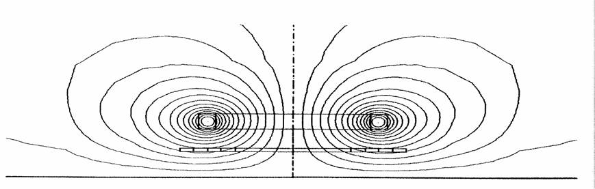
Fig. 2 - Plot of the flux distribution due to the superconducting
coil,
z = 0.25 m, d=0.10 m. |
Fig. 3 - Vertical acceleration PSD for A=1.25 10-6 m
and v = 100 m/s. |
|
|
Main contributions |
|
|
|
Ø Performance
evaluation of combined active and passive damping
Ø Active
damping performed by a coil current control using mechanical or
electrical transducers
Ø Analysis
of a control system for active damping which does not require vertical
position, velocity or acceleration measurement
Ø Control
system operation based on sensing the current in the damping coil and
regulating the supply voltage according to a suitable control law
Ø Stability
analysis
Ø Evaluation
of the effectiveness of the levitation system by analysing the Power
Spectral Density (PSD) of the vertical acceleration . |
|
|
PERMANENT MAGNET ACTUATORS:
REDUCTION OF THE TORQUE RIPPLE BY A MULTI-OBJECTIVE MINIMIZATION
TECHNIQUE
|
|
|
|
The demand for high performance
Permanent Magnet (PM) motors is continuously increasing in industrial
applications because of their high efficiency and power density. The
machine inherently has a torque ripple which causes vibrations and noises.
This deteriorates the performance of position control systems and speed
control systems at low speed. As a consequence, it is important to find
out methods for reducing the torque ripple to acceptable values.
With reference to sinusoidal PM
machines with surface-mounted magnets, there are mainly two contributions
to the torque ripple. The first one is the cogging torque which arises
from the interaction of the magnets with the stator teeth. As a result,
the torque is generated by the tendency of the rotor to align with the
stator at positions where the permeance of the magnetic circuit is
maximized. The second contribution is the torque ripple caused by the
presence of harmonics in the air-gap flux density distribution of the
magnets, which leads to non-sinusoidal components of the Electromotive
Force (EMF).
Many studies concerning the
analysis of the cogging torque have been carried out. The most effective
solutions proposed for the cogging torque reduction are the adjustment of
the magnet arc width relative to the slot pitch, the shifting of the pole
pairs and the skewing of either the stator slots or the rotor magnets.
Other methods which have been proposed for reducing the cogging torque
include the presence of dummy slots or dummy teeth in the stator
laminations, and the shaping of rotor magnets.
The influence of field
harmonics on the induced EMF may also be reduced acting on the stator
winding distribution or adopting a fractional number of slots per pole.
The skewing of stator slots and rotor magnets can also be used to reduce
the harmonic content of the induced EMF. However, the impact of all these
techniques cannot be considered separately for the two contributions to
the total torque ripple. A tight relationship between the two
contributions exists. The solutions employed to reduce the cogging torque
also affect the torque ripple produced by the harmonic content of the
induced EMF. As a consequence, the problem of the torque ripple reduction
should be considered on the whole and in most cases a compromise has to be
made to minimize the total torque ripple.
In the research, the
minimization of the torque ripple is formulated as an optimization design
problem, without separating the different contributions. In order to do
this a two-step design procedure has been proposed. In the first step a
global minimization algorithm coupled to a one-dimensional field analysis
is utilized. The minimization technique is based on the Evolution Strategy
(ES) method. The minimization algorithm proposed considers the enhancement
of the fundamental component of the induced EMF and the minimization of
the two torque ripple contributions. A multi-objective problem is stated
and solved by means of a penalty technique.
Once the design unknowns have
been determined by the proposed procedure, the magnet arc width has been
further optimized to minimize the cogging torque. For this purpose a
two-dimensional Finite Element (FE) analysis has been used to determine
the flux density distribution of the magnets. |
|
Fig. 1 - Plot of the rotor geometry (solution
A). |
Fig. 2 - Plot of the magnetic field
(solution A) |
|
Fig. 3
- Schematic drawing of the magnet skewing. |
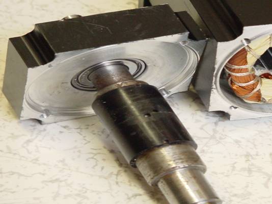
Fig. 4
- Prototype realized on the basis of the results
obtained for Solution B. |
|
|
The example presented
considers a 3-phase, 6-pole PM synchronous machine with sinusoidal EMF
and magnets placed on the rotor surface. Since the stator skewing
increases the complexity of machine construction, a skewed mounting of
discrete magnet segments on the rotor has been considered.Two
different magnet arrangements have been investigated. In the first
one, the sum of the magnets’ width is smaller than the rotor periphery
length. In the second one, the sum of the magnets width is equal to
the rotor periphery length. Therefore, the rotor surface is completely
covered by the PMs. This configuration allows the realization of the
magnetic part of the rotor using a tube of a polymer bonded magnetic
material and simplifies the manufacturing of the motor, since the
magnet material can be directly molded onto the rotor eliminating
subsequent assembly steps. In this work, the analysis will be mainly
focused on the second magnet arrangement type.
Experimental tests of the machine constructed by
means of the design procedure described, have been done. The test
results meet the design requirements.
|
Fig. 5
- Cogging torque
Fig. 6 - Cogging torque curves for Solution B. |
|
|
|
|
MAIN CONTRIBUTIONS |
|
|
|
Ø
Minimization of
the torque ripple, formulated as an optimization design problem
Ø
Minimization of
the torque ripple without separating the different contributions
Ø
Definition of a
two-step design procedure
Ø
Minimization
technique based on the Evolution Strategy (ES) method.
Ø
Multi-objective
problem solved by means of a penalty technique
Ø
Optimization of
the magnet arc width in order to minimize the cogging torque
Ø
Use of a
two-dimensional Finite Element analysis to determine the flux density
distribution of the magnets. |
|
|